| Brief Description | |
|---|---|
|
File: \examples\Processing\DebuggingAndTest\TriggerAndImageStatistics.va |
 |
|
Default Platform: mE5-MA-VCL |
|
|
Short Description Analysis of trigger and Camera Link functionalities is provided. The user can analyze the image data stream of a grayscale camera in Camera Link base configuration. The design is intended for the use in hardware only. |
|
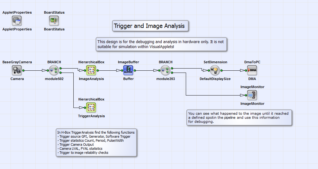
With the example design "TriggerAndImageStatistics.va" the analysis of trigger and Camera Link functionalities like number of pulses, signal width and period is possible. Also the difference between trigger and Camera Link signals is measured. The user can choose for the generation of the trigger signal between a software trigger, a trigger generator or an external source. In this design the user has furthermore the possibility to analyze the image data stream of a grayscale camera in Camera Link base configuration. The design is intended for the use in hardware only. It is not intended for the simulation within VisualApplets. This design is suitable to be a debugging "add-on" for image processing designs. In the following the functionalities of "TriggerAndImageStatistics.va" are explained. Its basic design structure is shown in Fig. 288.

In the HierarchicalBox ImageAnalysis the image data stream of a grayscale camera in Camera Link base configuration is analyzed. Image properties of the current frame but also of a complete image sequence, like image dimensions and line length deviations between single frames, are measured there. The frames are sent to PC via DMA. Furthermore the user has the possibility to monitor the image at a any defined point in the pipeline using the debugging operator ImageMonitor. In the HierarchicalBox TriggerStatistics the properties of the trigger signal and also of Camera Link signals like LVAL and FVAL are measured. Please see Fig. 289 for the content of box TriggerAnalysis.
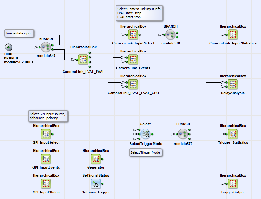
Here in box CameraLink_LVAL_FVAL the LVAL and FVAL signals are defined. At beginning and end of each image line and each frame a signal is generated with operators LineStartToSignal/ LineEndToSignal and FrameStartToSignal/FrameEndToSignal. The operator RsFlipFlop combines the corresponding start/stop signals to the LVAL and FVAL signals, which the user can monitor as events. These events are defined in the HierarchicalBox CameraLink_Events with the operator EventToHost. In the box CameraLink_LVAl_FVAL_GPO the LVAL and FVAL signals are assigned to the GPO and Front GPO with PinID 1. The statistics of the LVAL and FVAL start and stop pulses are defined in the HierarchicalBox CameraLink_InputStatistics. You can see the content of this box in Fig. 290.
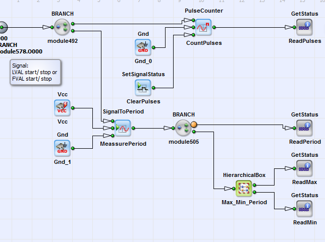
The number of pulses is here counted with operator PulseCounter. The user can monitor this number via the operator GetStatus_ReadPulses. The period between LVAL or FVAL start or stop pulses is defined with operator SignalToPeriod. The user can monitor this value via operator GetStatus_ReadPeriod together with its maximum and minimum values via GetStatus_ReadMax and GetStatus_ReadMin. Beside the monitoring of the statistics of the Camera Link signal, the user can observe the statistics of the trigger signal. The trigger signal can be generated using a trigger Generator, a SoftwareTrigger or external trigger source via GPIs, which can be selected in GPI_InputSelect. The user can monitor the GPI input events and the input status (see boxes GPI_InputEvents and GPI_InputStatus). The trigger signal is applied to the camera control and GPOs in HierarchicalBoax TriggerOutput. The user can monitor the statistics of the trigger signal as defined in the HierarchicalBox Trigger_Statistics. You can see its content in Fig. 291.
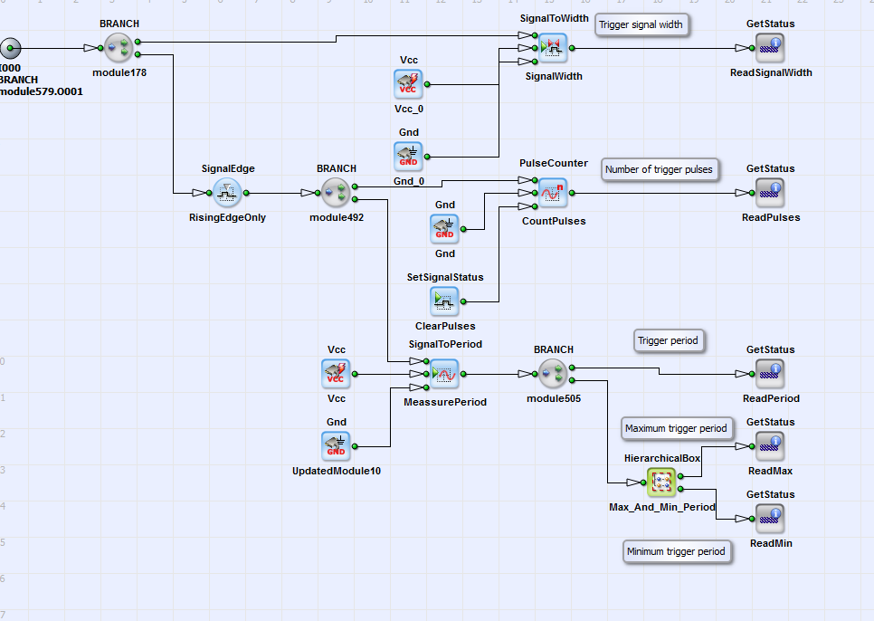
Here the trigger signal width is defined (see SignalToWidth operator SignalWidth). The user can observe this value via GetStatus operator ReadSignalWidth. The number of trigger rising edge pulses is counted with PulseCounter. The user can have a look at this number via GetStatus operator ReadPulses. This is also true for the period between the trigger rising edge pulses, its maximum and minimum value (see GetStatus operators ReadPeriod, ReadMax, ReadMin). Coming back to Fig. 289. In the HierarchicalBox DelayAnalysis the CameraLink signals and the trigger signal are compared. You can see the content of DelayAnalysis in Fig. 292.
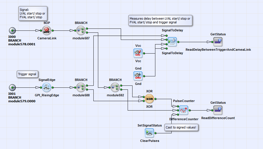
Here the delay between LVAL or FVAL start or stop signal and the trigger rising edge is measured. The user has access to this value via a GetStatus operator. Also the difference number of pulses between between the two signal is measured. If the user observes a value of ReadDifferenceCount greater than one, the trigger signals have been sent but the camera did not respond. If this value is smaller than 1 the camera sent more frames or lines than trigger pulses came in. Beside the analysis of trigger and Camera Link signals, the analysis of image data stream is implemented in "TriggerAndImageStatistics.va" in the HierachicalBox ImageAnalysis (see Fig. 288). You can see its content in Fig. 293.
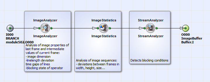
The operator ImageAnalyzer gives you the possibility to analyze the image properties of the last frame and the intermediate values of the current frame. These properties are image dimensions, line length deviations and time gaps of lines. This operator gives you also information on the blocking state of the operator input. The operator ImageStatistics analyzes complete image sequences. Deviations in image dimensions line gaps etc. are measured. The operator StreamAnalyzer gives you information on the data flow and blocking conditions. During the analysis the image data are not touched.
